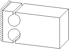
The flexure hinge is a proven design element in precision engineering systems. It is created by drilling or spark erosion of two adjacent holes.
The positive characteristics of flexure hinges, free of backlash and friction, are partially offset by the limited angular rotation. To properly size a flexure hinge, an optimum must be found between the desired angular rotation, stiffness, and maximum material stress. It often takes some calculations to find a satisfactory design. Several formulas are available for this purpose. They are based on theoretical solutions of force equations or on approximations of finite element analysis (FE) results..
Theoretical Stiffness Calculation
Calculating the stiffness of a flexure hinge and the material stress that occurs under load is a very complex matter. Over the years, many articles have been published on solving the force equations applicable to the flexure hinge. The article by J.M. Paros and L. Weisbord (How to design flexure hinges, Machine Design, November 25, 1965) is among the best known. N. Lobontiu, Wu and Zhou, and Tseytlin also derived formulas for calculating flexure hinges..
One limitation of these theoretical approaches is that the flexure is analyzed in isolation, which means that any distortion in the base material adjacent to the contracted part of the flexure is not considered. For the design engineer, this means that the stiffness of the flexure hinge will be lower in practice..
Practical Approach by Using FE-Analysis
An accurate calculation of the stiffness of a flexural hinge can be important for practical applications. The lecture notes ‘Predicting dynamic behavior and positioning accuracy of constructions and mechanisms‘, W. van der Hoek 1981″ provide empirical equations (based on FE analysis) for calculating stiffness and material stress values. An article (Review of circular flexure hinge design equations and derivation of empirical formulations, 2007) compares various theoretical and empirical approximations. In this article, he refers to an article by W.O. Schotborgh et al. using the empirical formulas of W. van der Hoek. Yong concludes that these empirical formulas give the highest accuracy, with a margin of error of <2.5%. Since these formulas are also easy to apply, they are very practical for a design engineer.
The FlexHinge freeware, which was developed by Vink System Design & Analysis and which you can download and use for free from this website after registration, uses these empirical equations.